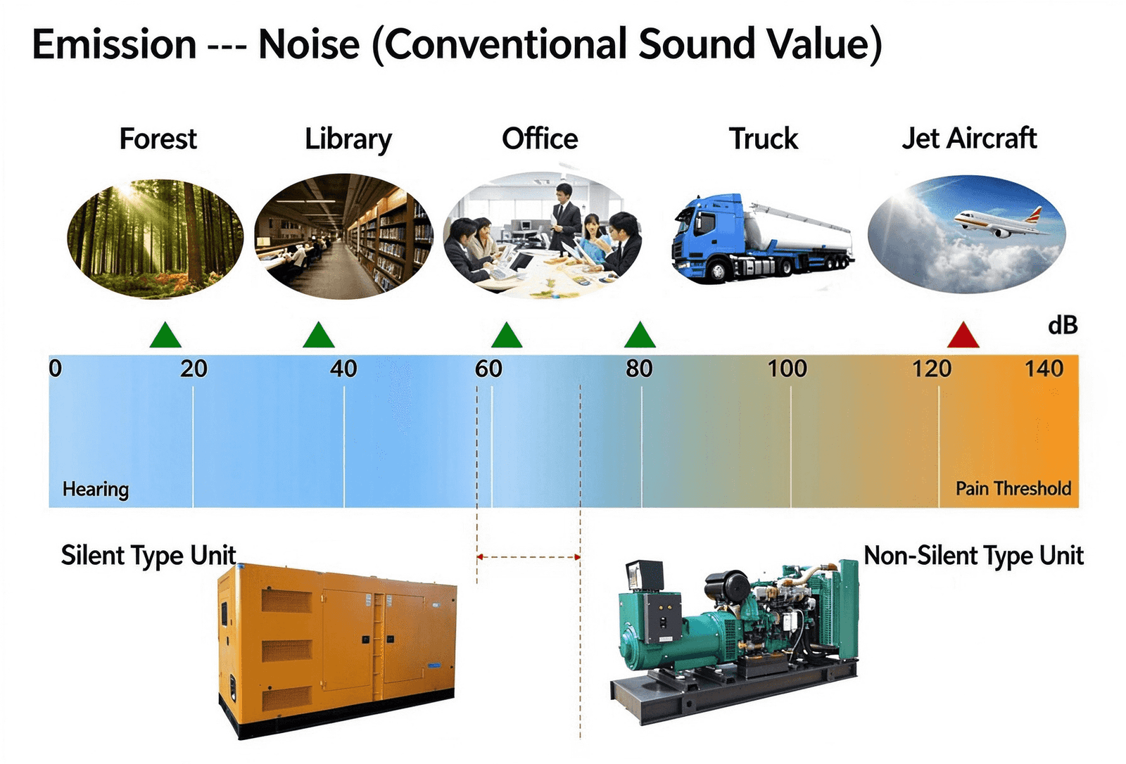
I. Where the Noise Comes From: The Four Types of Sound Sources to Control
(1) Exhaust noise: generated when high-temperature, high-pressure exhaust gas is discharged; it is the single most intense noise source and the most difficult to control.
(2) Mechanical and combustion noise: piston slap, gear meshing, abrupt combustion-pressure changes, and similar phenomena radiate outward through the engine body itself.
(3) Cooling-fan noise: aerodynamic noise produced by fan rotation, directly related to rotational speed and blade design.
(4) Structure-borne (vibration-transmitted) noise: the set’s vibration travels through the base, piping, and building structure, creating “secondary noise” at a distance.
II. Noise Reduction Principles of Silent Generator Sets: Four-Layer Coordination of Insulation, Absorption, Silencing, and Isolation
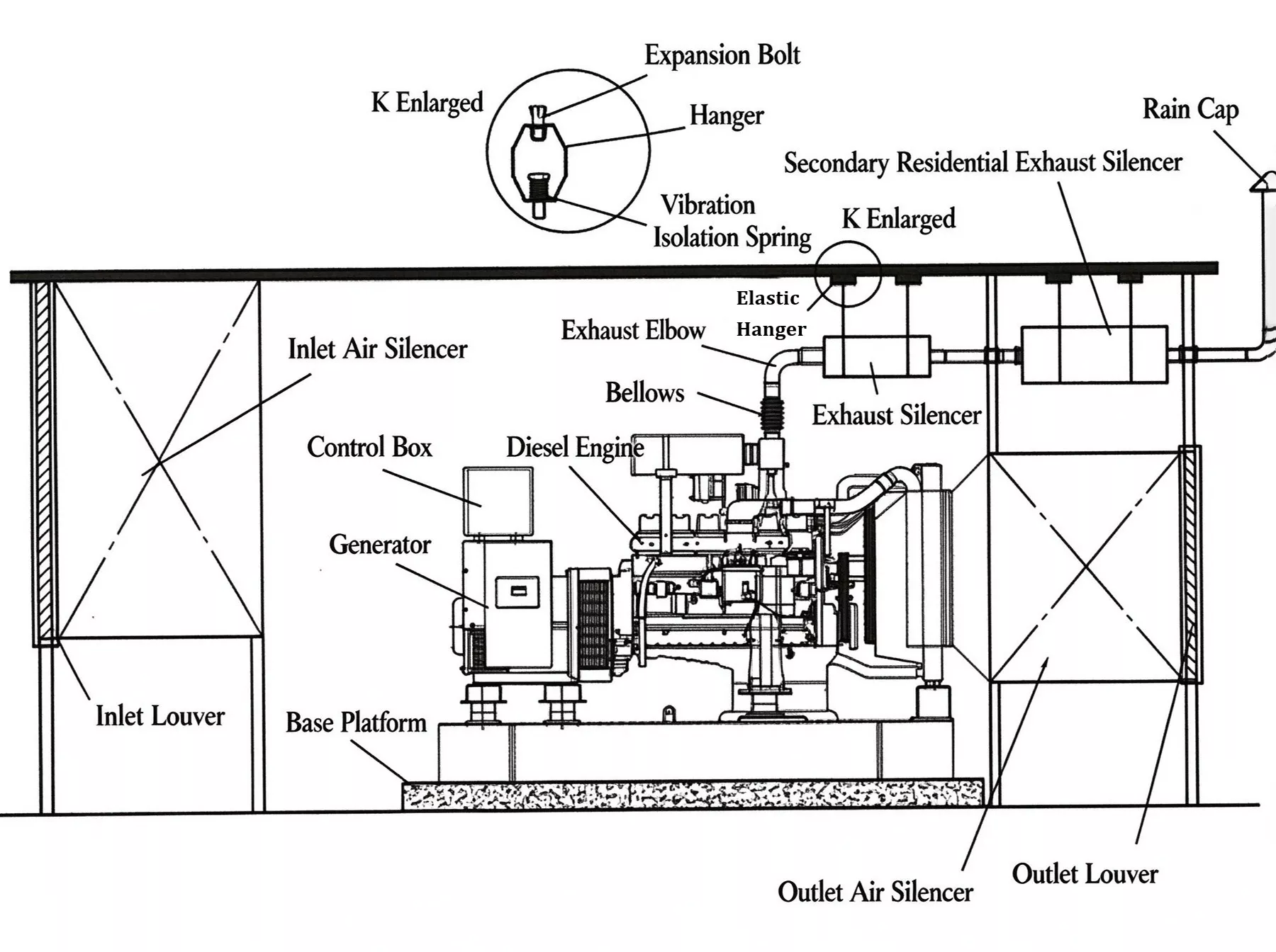
(1) Sound-insulation layer — blocks sound transmission. The enclosure shell uses high-surface-density steel plate or other sound-insulating materials, exploiting the mass law to block sound-wave penetration. The inner side of the steel plate is usually coated with a damping compound to suppress the plate’s own resonance and prevent “panel resonance” from amplifying noise instead.
(2) Sound-absorption layer — absorbs in-box reverberation. A porous sound-absorbing material (e.g., glass wool, rock wool, polyester-fiber cotton) is laid on the inner side of the insulation layer to absorb the sound energy repeatedly reflected inside the enclosure, preventing sound from building up and amplifying within the sealed space. Patent literature also describes specific implementations such as PUR-type flame-retardant acoustic foam and honeycomb-shaped acoustic-cotton layers.
(3) Silencing duct — lets air pass while retaining the sound. The set must dissipate heat, so intake and exhaust ducts cannot be sealed shut. The common industry practice is to install resistive plate-type silencers or labyrinth-style silencing ducts at the air inlet and outlet, consuming sound energy with absorbent material while guaranteeing ventilation volume. On the exhaust side, an impedance-composite (reactive-dissipative) silencer is installed (a reactive silencer for mid-to-low frequencies, a dissipative silencer for mid-to-high frequencies); this is the most critical link in controlling exhaust noise.
(4) Vibration isolation — cuts off the solid sound-transmission path. Rubber vibration-isolation pads or spring isolators are installed between the set’s base and its foundation; all exhaust, fuel, and water pipes connected to the set use flexible connections (such as metal bellows) to prevent vibration from propagating through the structure to distant locations.
III. Site Selection for Silent Generator Sets: From the 7 m Nominal Noise Level to the Actual On-Site Level
Therefore, site selection for a silent set must consider both distance attenuation and reflection effects:
(1) Keep away from noise-sensitive receptors: the set should be placed as far as possible from offices, residential areas, hospitals, and other noise-sensitive targets; where conditions allow, maintain a distance of at least 20 m.
(2) Avoid wall-mounted installation: keep a safety clearance of 1.5–3 m between the set and buildings or fences, balancing noise reduction with maintenance access; the side of a building facing away from the sensitive point, as well as terrain or green belts, can be used as additional barriers.
(3) Use terrain and barriers: positioning the set on the side of a building facing away from the sensitive point, or using terrain and green belts as additional barriers, can further reduce the noise at the receiving point beyond what distance attenuation alone achieves.